Skip to main content
 RVS 3.24 accelerates multicore software verification
 Rapita Systems and Avionyx Announce Strategic Partnership to Offer Best-in-class Avionics Solutions
 Rapita System Announces New Distribution Partnership with COONTEC
 RVS gets a new timing analysis engine
 How to measure stack usage through stack painting with RapiTest
 What does AMACC Rev B mean for multicore certification?
 How emulation can reduce avionics verification costs: Sim68020
 How to achieve multicore DO-178C certification with Rapita Systems
 How to achieve DO-178C certification with Rapita Systems
 Certifying Unmanned Aircraft Systems
 DO-278A Guidance: Introduction to RTCA DO-278 approval
 Test what you fly - Real code, Real Conditions Webinar
 Avionics Certification Q&A: CERT TALK
 XPONENTIAL 2026
 DO-178C Multicore In-person Training (Heathrow)


"Data coupling" and "control coupling" (collectively “DCCC”) refer to the way software components interact with each other in an integrated system to perform a higher-level function. Understanding software DCCC and analyzing DCCC coverage during integration testing can help reduce development costs and mitigate risks, and DCCC analysis is required for DO-178C certification of critical avionics. Rapita Systems is developing RapiCoupling , an automation solution designed to meet the complexities of DCCC analysis for modern DO-178C software.
This post can be regarded as a companion post to the previous one, which provided an introduction to control coupling. It provides a closer look at data coupling.
Data Coupling generally relates to how data values propagate and are transformed between components. DO-178C includes the following definition for data coupling:
“Data Coupling is the dependence of a software component on data not exclusively under the control of the software component.”
But what does this actually mean?
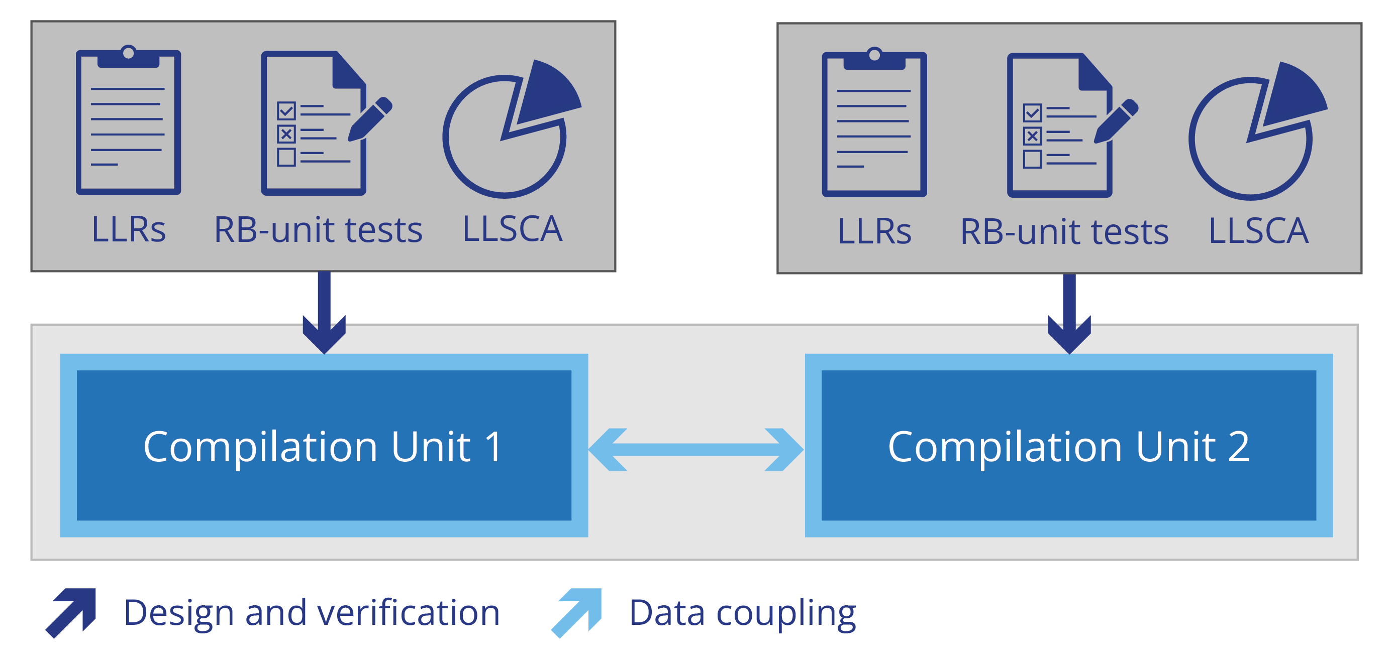
The different ways data can flow through a software architecture, from component to component, depends on the way the software components are integrated. The simplest type of software integration is the single threaded execution model, usually based on compilation units (or pre-compiled libraries) integrated together with a linker. Here, each software component’s functions call other functions, possibly in other components, which in turn execute and return control back to the calling component. Software components can be integrated in more complex ways, for example interrupt processing, multi-tasking and multi-threading. We’ll take a closer look at some of these execution models in subsequent posts.
Data can be shared between components in multiple ways, including via:
- Statically allocated global variables
- Stack, i.e. parameters and return values
- Heap, i.e. dynamically allocated and accessible via pointers or references
Data coupling is one of the ways of demonstrating that high-level testing is sufficiently comprehensive. The main inspiration for suitable metrics for data coupling as coverage criteria is the research done on dataflow coverage(see for example (Su et al 2017) for a survey).
One of the most popular criteria for measuring data coupling coverage is definition-use pairs, where the notion of coverage is based on the ways data values are produced in one component and consumed in another. Under the strictest definition-use interpretation, all write/read pathways, where the data item acquires its value at the write and then the value is first referred to at the read, must be exercised in testing.
Definition-use Pairs
Let’s start with three basic examples.
Example 1. Data Coupling via a global variable
Data can be written to a global variable in a function in one component and used by a function in another component. As the latter function depends on data written by the former, a data dependency exists between the two functions, and data couplings exist between the last potential write locations to the global variable and the first potential read locations from the global variable. Couplings represent the different ways data can be transferred between the components, and these may be used as coverage criteria. By achieving definition-use coverage, we can gain confidence that we have observed all of the possible ways that variables can acquire and provide their values.
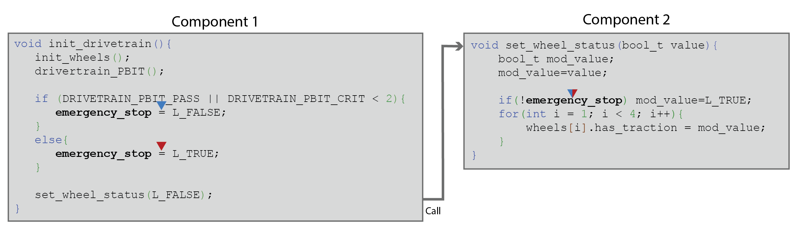
This idea can be illustrated with the above example, which sets a global variable emergency_stop in one of two possible ways before calling code in another component that references the value of the global variable. The triangles shown on the code mark the starts and ends of the paths that need to be observed in testing for the couplings to be considered covered.
Example 2. Data Coupling via a passed parameter
When a call is made from a function in one component to a function in another component, parameters can be passed to the called function. As the destination function depends on these values, a data dependency (dataflow) exists between the origin and destination components. In this case, no global variables are necessarily involved, and the stack is acting as the globally accessible memory via which the data flows. The major difference between data coupling on global variables and data couplings on parameters is that the variables on either side of the dataflow usually have different names.
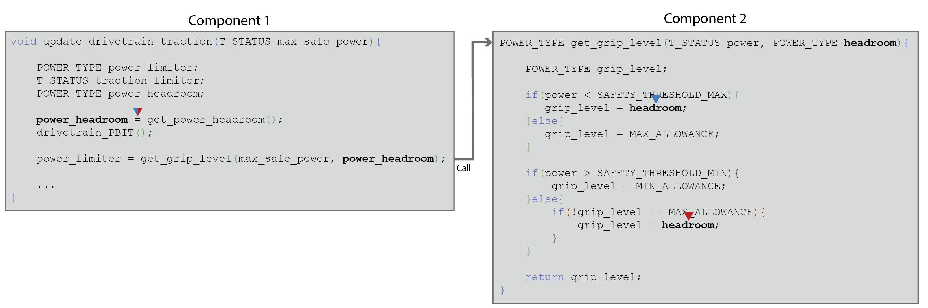
Parameter data coupling can be illustrated with the above example, in which a parameter ( power_headroom) acquires its value via a definition in one component, a transfer of control takes place across a component boundary, and the value is passed to another component. The parameter is now referred to by the name declared in the signature of the destination function ( headroom) and referred to in two places within the body of the function.
Example 3. Data Coupling via return of control
Calls from one component to another component are not the only form of transfer of control in call-return interfaces; the return of control is another mechanism that can introduce data dependencies. Global variables can be set in called functions that are then used in calling functions downstream of the call. In addition, called functions can return values that are subsequently used, or, for example, set memory allocated in heap by dereferencing pointer parameters.
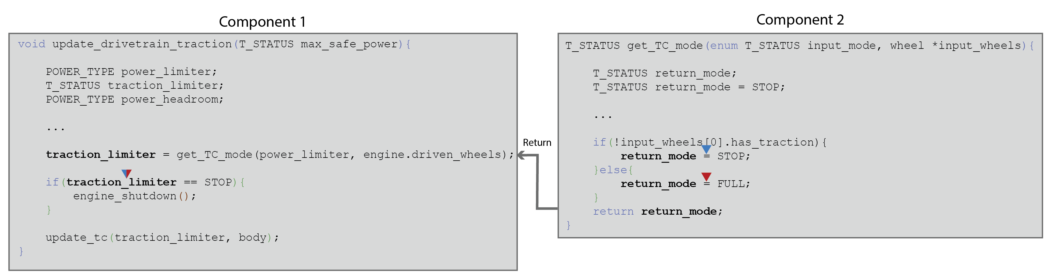
An illustration is presented in the above example, in which a called function sets a return value ( return_mode) at two possible sites in the code and then returns it to the calling function, where is it subsequently used ( traction_limiter).
Definition-use Arity
When looking at code coverage metrics based on definition-use criteria, there are multiple considerations. One key consideration is the arity of the metric applied, which corresponds to which paths you consider you need to have observed to deem your testing sufficient. There are broadly three interpretations of sufficient based on whether you must observe:
- Any single path between a definition and a use;
- A set of paths between definitions and uses that executes all definitions and all uses at least once;
- Every definition-use path, i.e. you must have observed a path between every definition and each of its potential uses.
This strategic choice is sometimes referred to as a decision between:
- Any-any (the least onerous interpretation)
- D+U (the intermediate interpretation)
- D*U (the most onerous interpretation)
There can be several additional variants to consider, too, such as how different transfers of control between definition and use are incorporated into the metric, and whether redefinition without use (or reuse without definition) are treated as special cases.
Further complications and variants can arise from, for example:
- How you interpret writes to and reads from compound data items, such as structs or arrays
- Where parameters are involved, how you define the position in the code at which a value is defined; e.g. this could be defined as the expression in the argument or writes to the variables it depends on.

Preview
An innovative new approach for DCCC Analysis
- Data coupling and control coupling analysis for DO-178C
- Configurable definition of components, interfaces and couplings
- Process guidance to help define couplings for your project
Coupling Feasibility
While applying simple definitions as to what constitutes a coupling can make automated analysis straightforward, this can result in couplings that cannot be covered in testing. This can increase effort unduly, for example the effort needed to investigate the causes and provide arguments for why coverage obligations remain uncovered.
Uncoverable goals can result from a variety of sources, including:
- Which paths are executable between writes and reads across a cross-component transfer of control (especially when those writes and reads are non-local to the call)
- Complexities, such as aliasing, introduced by pointers
Other metrics
Combinations of writes to and reads from variables are not the only basis for coverage of the data flowing over an interface. An example of another kind of metric is equivalence classing, where values associated with data flow over component boundaries are partitioned into their significant subsets. The observation criteria, which may be used in conjunction with definition-use-style criteria, is to see examples of data flow in each identified subset during testing.
Examples for single data items include:
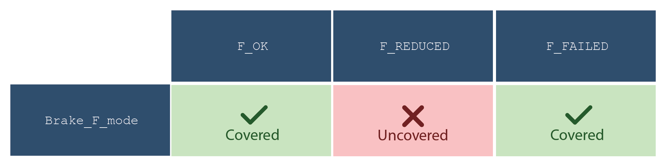
- Modes of operation, such as failure modes;
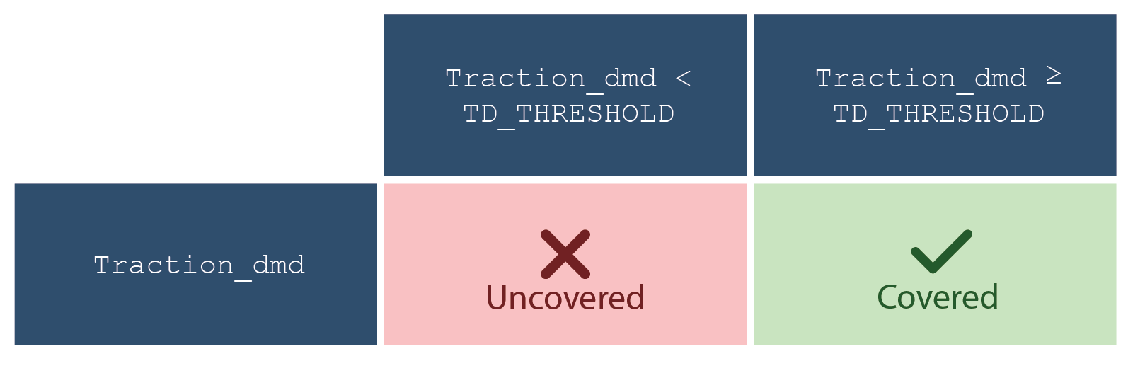
- Range partitioning, such as whether the item is below, equal to, or above a threshold;
Examples of multiple data items include:
- (item 1, item 2) in Class A X Class B – where we may want to observe an example of pairs of values in every pair of partitions, i.e. if Class A consists of partitions P 1, P 2, P 3, and Class B consists of partitions Q 1, Q 2, Q 3, then observe pairs of items in (P 1, Q 1), (P 1, Q 2), (P 1, Q 3), (P 2, Q 1), (P 2, Q 2), (P 2, Q 3), (P 3, Q 1), (P 3, Q 2), (P 3, Q 3).
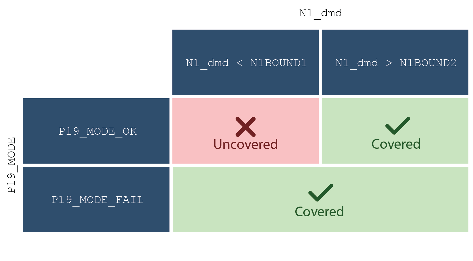
- More general relationships between data items, such as “item 1 in range 1 when item 2 is mode 1; item 2 is mode 2” (Figure 6)
With definition-use pairs, observation goals can be derived directly from the code. The challenges are usually deciding and justifying which variant is appropriate and eliminating infeasible couplings. With equivalence class style criteria, it is less clear where observation goals can be derived from. Two strategies are:
- Deriving observation goals from the LLRs of the component at the target end of the data flow, for example based on the conditions under which particular LLRs are applicable. This provides a kind of LLR coverage, which provides assurance that the LLRs themselves have been stipulated correctly to satisfy the HLRs.
- Deriving observation goals from the code using static analysis or heuristics, for example based on analysis of the branch conditions in the code, with the aim of maximizing which branches are executed.
Common Defect Absence
The most general interpretation of data coupling is that it is a means of providing evidence of the absence of defects associated with data flow. Based on (Rierson 2013), common defects for call-return type interfaces might include, for example
- Units are consistent and agree with data dictionary
- Data is typed correctly/consistently
- Data is initialized or read in before being used
- Data is sent and received in the right order
Much of the work eliminating defects, such as that to show that engineering units have been captured consistently between components, is necessarily review-focused. This is because it is not always straightforward to define measurements within executing code that can provide meaningful evidence of the absence of a particular sort of defect.
You can, however, gain confidence that certain types of defect are absent by other means. Static analysis, for example, can allow you to check usage and initialization before use at the global level where linkers often fail to provide such assurances. You can also use direct measurement during test to confirm that data flows between components are behaving correctly: for example, that data values are sub-typed correctly, as defined in the data dictionary, and that data is not referenced before it has been set (such as when static analysis proves too complex, e.g. reference via pointers). You can check the ordering in which data is set and referenced during execution to confirm it respects any required constraints on sequencing.
What constitutes confirmatory evidence of correct interface behavior is open to question. A single confirmatory test of correct behavior is a weak basis for arguing the absence of defects, however if it can be demonstrated that all tests confirm the behavior, where testing has itself been shown sufficient with respect to an independent criterion, this can be provide a much stronger basis for the absence of defects.
Conclusion
This blog provides an introductory discussion to what data coupling analysis entails. It necessarily provides a simplified view restricted to a single interface type. More detail will be provided in subsequent blog posts, including how to think about data coupling analysis over more elaborate interfaces than call-return interfaces.
With data coupling, as with control coupling, many questions arise that have no clear answer. It is ultimately up to each certification applicant to determine (and agree with their DER) how they will approach data coupling and what coverage metrics they will provide as evidence. Rapita is collaborating with organizations including Collins Aerospace to provide guidance on best practice for DCCC analysis. For more information, see our presentation at the Digital Avionics Systems Conference (DASC) 2024 (Galloway et al 2024).
Wanting to learn more about DCCC? Check out our full blog series or download our DCCC Solutions for DO-178C Product brief.
Want to stay up to date with DCCC content? Sign up to our mailing list below.
References
[1] T. Su et al., “A Survey on Data-Flow Testing,” ACM Comput. Surv. 50, 1, Article 5 (March 2017)
[2] Rierson, L. (2013) Developing Safety-Critical Software: A Practical Guide for Aviation Software and DO-178C Compliance. CRC Press
[3] A. Galloway et al., “Defining Quantifiable Measures for Data Coupling and Control Coupling,” AIAA DATC/IEEE 43rd Digital Avionics Systems Conference (DASC) 2024, pp. 1-10, doi: 10.1109/DASC62030.2024.10749159
DO-178C webinars

White papers
Mitigation of interference in multicore processors for A(M)C 20-193

Developing DO-178C and ED-12C-certifiable multicore software

Efficient Verification Through the DO-178C Life Cycle

A Commercial Solution for Safety-Critical Multicore Timing Analysis